


Description
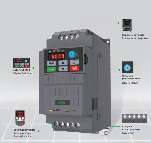
WK200 FREQUENCY INVERTER PRODUCT APPEARANCE INTRODUCTION
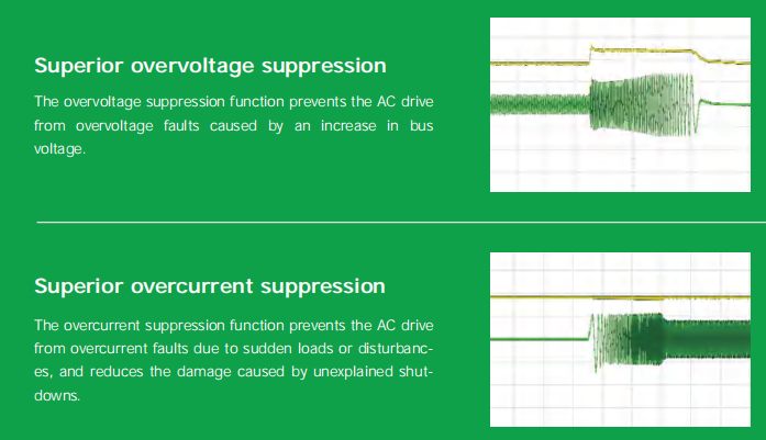
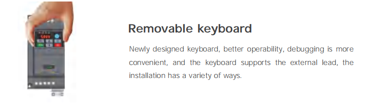
With built-in hardware protection features including output-to-ground short circuit protection, internal buffer relay protection, fan drive circuit protection, motor overload protection, phaseloss protection, overheat protection, overvoltage protection, overcurrent protection, undervoltage protection, the AC drive provides comprehensive protection for both internal and external devices.
WK200 VFD INVERTER TECHNICAL SPECIFICATIONS
Power input | Rated input voltage | 200V Voltage Class:single/three-phase 200V ~ 240V |
400V Voltage Class:Three-phase 380V~440V | ||
Frequency | 50Hz/60Hz, tolerance ±5% | |
Voltage range | -15%~+15% | |
Voltage out-of-balance rate<3%, distortion rate as per the requirements of IEC61800-2 | ||
Rated input current | See Section 2.3 | |
Power output | Applicable motor (kW) | See Section 2.3 |
Rated current (A) | See Section 2.3 | |
Output voltage (V) | 3-phase:0%~rated input voltage, error < ±3% | |
Output frequency (Hz) | 0.00%~600.00Hz; unit:0.01Hz | |
Overload capacity | G type:150% – 60 seconds, P type:120% – 60 seconds | |
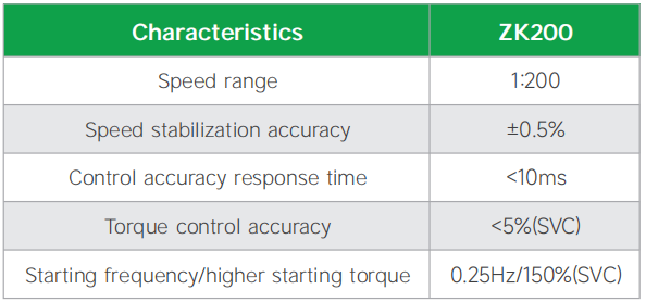
Control characteristics | Control mode | V/f control Sensorless vector control (SVC) |
Range of speed regulation | 1:200 (Sensor-less vector control ) | |
Speed accuracy | ±0.5% (Sensor-less vector control ) | |
Torque control accuracy | 5%(SVC) | |
Torque increase | Automatic torque lifting; Manual torque increased by 0.1-30.0% | |
Starting torque | 0.25Hz:150% (Sensor-less vector control ) | |
Basic functions Basic functions | Output frequency | 0.00~600.00Hz |
ACC/DEC time | 0.00~30000s | |
Carrier frequency | 0.5kHz~16kHz | |
Frequency setting | Digital setting + Keyboard Control Communication Analog setting Terminal pulse setting | |
Motor start-up methods | Started from starting frequency DC brake start-up Speed tracking start | |
Motor stop methods | Ramp to stop Free stop | |
Dynamic braking capacity | Brake unit working voltage: 200V level:325-375V / 380V level:650V-810V Service time:0-100.0s; | |
DC brake capacity | DC brake start frequency:0.00~600.00Hz DC brake current:0.0~100.0% DC brake time:0.0~100.00s | |
Input terminals | 4 digital inputs, one of which can be used for high-speed pulse input 1 analog inputs, which is voltage/current optional | |
Output terminals | 1 digital output terminal, 2 Relay output terminal,1 analog output ,Voltage and current outputs are optional, supporting 0~10V voltage or 0/4~20mA current outputs. | |
Communication terminal | 1 channel RS485 communication (standard), can support up to 38400bps communication rate | |
Featured functions | Parameter copy, parameter backup, common DC bus, parameters, flexible parameter displayed & hidden, various master & auxiliary setting and switchover, flying start, a variety of Accel/Decel curves optional, brake control, 16-step speed control programmable (2-step speed supports flexible frequency command), wobble frequency control, fixed length control, count function, three history faults, over excitation brake, over voltage stall protection, under voltage stall protection, restart on power loss, skip frequency, frequency binding, four kinds of Accel/Decel time, motor thermal protection, flexible fan control, process PID control, simple PLC, multi-functional key programmable, droop control, autotuning,field-weakening control, high-precision torque restraint, V/f separatedcontrol | |
Protection functions | Refer to Chapter 6-Trouble Shooting | |
Environment | Place of operation | Indoors, no direct sunlight, free from dust, corrosive gases, flammable gases, oil mist, water vapor, water drop or salt, etc. |
Altitude | 0~2000m. De-rate 1% for every 100m when the altitude is above 1000 meters | |
Ambient temperature | -10℃~50℃, The rated output current should be derated 1% for every 1℃ when the ambient is 40℃~50℃ | |
Relative humidity | 5~95%, no condensation | |
Vibration | Less than 5.9m/s² (0.6g) | |
Storage temperature | -20℃~+60℃ | |
Others | Efficiency at rated Amps | Rated power 7.5kW and below:≥93% 11~22kW:≥ 95% |
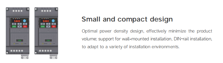
Installation | Standard: wall-mounted; Optional: 5.5kW and below DIN-Rail Mount, 7.5kW and above embedded installation | |
IP grade | IP20 | |
Cooling method | Forced air cooling,Natural cooling | |
WK200 LOW FREQUENCY INVERTER PRODUCT FEATURES
VSD Integration of speed andtorque control
three phase frequency converter Torque and speed control performance- to ensure smooth mechanical operation, rapid response, small torque pulsation.
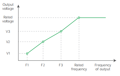
VSD Adaptive Vector Control
Vectorized performance with VF convenience. Motor parameters insensitive, no self-learning required.
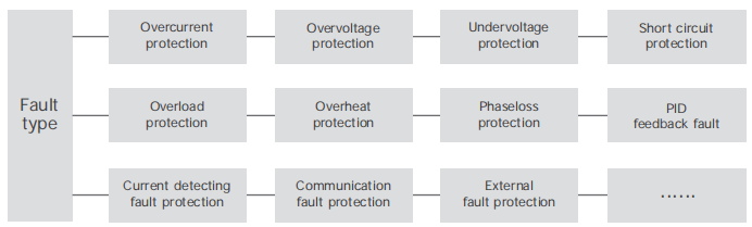
Protection Functions
With hardware protection functions such as output-to-ground short circuit protection, internal buffer relay protection, fan drive circuit protection, motor overload protection, phaseloss protection, overheat protection, overvoltage protection, overcurrent protection, undervoltage protection, etc., it realizes all-around protection for the internal and peripheral devices of AC drive.
Superior performance of WK frequency inverter
Structural & Hardware Features structural & Hardware Features
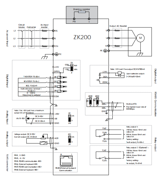
Function description of the control terminals
| Category | Terminal | Terminal Name | Function Description |
| Power source | 10V-GND | +10V power supply | 1,External 10V power supply |
| 2,Generally used for external potentiometer power supply, potentiometer resistance range 1kΩ~10kΩ | |||
| 3,Maximum output current 20mA | |||
| 24V-COM | +24Vpower supply | 1,Provide +24V power supply to external unit. Generally, it provides power supply to DI/DO terminals and external sensors. | |
| 2,Maximum output current:100mA | |||
| 3,Do not use this power supply as an external power supply | |||
| Analog | AI1 | Analog input terminal | Supports 0V to 10V voltage or 0/4mA to 20mA current input, which is selected by jumper AI1(J10). The default voltage input is 0V to 10V |
| input | |||
| Digital input | DI1 | Digit input terminal 1 | 1,Multifunctional digital input, through F5-00 to F5-03 to set the function |
| DI2 | Digit input terminal 2 | 2,Supports external NPN and PNP input. You can select the input mode by using jumper DI(J1). By default, the input mode is NPN | |
| DI3 | Digit input terminal 3 | 3,DI4 can be used as a pulse input terminal. This function is optional. | |
| DI4 | Digit input terminal 4 | ||
| Analog | AO1 | Analog output terminal | Support 0V~10V voltage or 0/4mA~20mA current output, selected by jumper AO1(J4), default is 0V~10V voltage output |
| output | |||
| Digital | DO1 | Digital output | 1,DO1 open-collector output |
| output | 2,Pull-up voltage range: 5V~24V (resistance range: 1kΩ~10kΩ) | ||
| 3,Output current range:0~50mA | |||
| Relay | T1/A-T1/C | Relay T1 normally open terminal | Contact drive capacity: AC250V, 3A; DC30V, 5A |
| Output 1 | T1/B-T1/C | Relay T1 normally closed terminal | |
| Relay | T2/A-T2/C | Relay T2 normally open terminal | |
| Output 2 | |||
| 485 communication | 485+ – 485- | RS-485 | 1,Standard RS-485 communication terminals, use twisted-pair shielded cables |
| 2,Terminal resistance 120R is selected by jumper 485R. The default is no terminal resistance | |||
| communication terminal | 3,Communication filter capacitor is selected by jumper 485C. The default value is no filter capacitor |
WK200 motor drive standard wiring diagram
WK200 frequency inverter Appearance, mounting dimensions and weight
| External dimensions | Installation dimensions (mm) | Mounting aperture | NW | |||||
| Model | (mm) | (mm) | (Kg) | |||||
| H | D | W | W2 | d | ||||
| Single-phase power supply:220V,50/60Hz Range:-15%~+15% | ||||||||
| WK200-2S-0.4GB | 142 | 123 | 75 | 66 | / | 132 | 5 | 0.9 |
| WK200-2S-0.75GB | 142 | 138 | 75 | 66 | / | 132 | 5 | 1 |
| WK200-2S-1.5GB | ||||||||
| WK200-2S-2.2GB | 180 | 151 | 90 | 80 | / | 167 | 5 | 1.4 |
| Three-phase power supply:220V,50/60Hz Range:-15%~+15% | ||||||||
| WK200-2T-0.4GB | 142 | 123 | 75 | 66 | / | 132 | 5 | 0.9 |
| WK200-2T-0.75GB | 142 | 138 | 75 | 66 | / | 132 | 5 | 1 |
| WK200-2T-1.5GB | ||||||||
| WK200-2T-2.2GB | 180 | 151 | 90 | 80 | / | 167 | 5 | 1.4 |
| Three-phase power supply:380V,50/60Hz Range:-15%~+15% | ||||||||
| WK200-4T-0.4GB | 142 | 123 | 75 | 66 | / | 132 | 5 | 0.9 |
| WK200-4T-0.75GB | 142 | 138 | 75 | 66 | / | 132 | 5 | 1 |
| WK200-4T-1.5GB | ||||||||
| WK200-4T-2.2GB | ||||||||
| WK200-4T-4.0GB | 180 | 151 | 90 | 80 | / | 167 | 5 | 1.4 |
| WK200-4T-5.5GB | ||||||||
| WK200-4T-7.5GB | 242 | 165 | 100 | 84 | 85 | 232 | 5 | 2.6 |
| WK200-4T-11GB | 320 | 181 | 116 | 98 | 98 | 307 | 5.5 | 3.5 |
| External dimensions | Installation dimensions (mm) | Mounting aperture | NW | |||||
| Model | (mm) | (mm) | (Kg) | |||||
| H | D | W | W1 | W2 | H1 | d | ||
| WK200-4T-15GB | 383 | 223.5 | 142 | 125 | 100 | 372 | 5.5 | 7 |
| WK200-4T-18.5GB | ||||||||
| WK200-4T-22GB | ||||||||
Information of WK200 inverter Product Model
| 1 Product model and technical data(three-phase 380V) | |||||
| Model | Power | Output current | Input current | Matched motor | Brake |
| rating (kW) | (A) | (A) | (kW) | unit | |
| WK200-4T-0.4GB | 0.4(0.75) | 1.5(2.5) | 1.9(3.5) | 0.4(0.75) | Inbuilt |
| WK200-4T-0.75GB | 0.75(1.5) | 2.5(3.8) | 3.5(4.6) | 0.75(1.5) | |
| WK200-4T-1.5GB | 1.5(2.2) | 3.8(5.1) | 4.6(6.3) | 1.5(2.2) | |
| WK200-4T-2.2GB | 2.2(3.0) | 5.1(7.1) | 6.3(8.6) | 2.2(3.0) | |
| WK200-4T-4.0GB | 4.0(5.5) | 9.5(13) | 12.1(16.8) | 4.0(5.5) | |
| WK200-4T-5.5GB | 5.5(7.5) | 13(17) | 16.8(22) | 5.5(7.5) | |
| WK200-4T-7.5GB | 7.5(11) | 17(25) | 22(32.5) | 7.5(11) | |
| WK200-4T-11GB | 11(15) | 25(32) | 32.5(41.5) | 11(15) | |
| WK200-4T-15GB | 15(18.5) | 32(37) | 41.5(49.6) | 15(18.5) | |
| WK200-4T-18.5GB | 18.5(22) | 37(45) | 49.6(59) | 18.5(22) | |
| WK200-4T-22GB | 22(30) | 45(60) | 59(65) | 22(30) | |
| 2 Product model and technical data(three-phase 220V) | |||||
| Model | Power | Output current | Input current | Matched motor | Brake |
| rating | (A) | (A) | (kW) | unit | |
| (kW) | |||||
| WK200-2T-0.4GB | 0.4 | 2.3 | 4 | 0.4 | Inbuilt |
| WK200-2T-0.75GB | 0.75 | 4 | 4.8 | 0.75 | |
| WK200-2T-1.5GB | 1.5 | 7 | 8.8 | 1.5 | |
| WK200-2T-2.2GB | 2.2 | 9.6 | 12 | 2.2 | |
| 3 Product model and technical data( single-phase 220V) | |||||
| Model | Power | Output current | Input current | Matched motor | Brake |
| rating | (A) | (A) | (kW) | unit | |
| (kW) | |||||
| WK200-2S-0.4GB | 0.4 | 2.3 | 5 | 0.4 | Inbuilt |
| WK200-2S-0.75GB | 0.75 | 4 | 8.2 | 0.75 | |
| WK200-2S-1.5GB | 1.5 | 7 | 14 | 1.5 | |
| WK200-2S-2.2GB | 2.2 | 9.6 | 23 | 2.2 | |


Reviews
There are no reviews yet.