


Description
WK300 Series High Performance Vector Drives
WK300 AC drives are unparalleled in their ability to accommodate an extensive range of motor types. This includes ordinary asynchronous motors, variable frequency motors, synchronous motors, high-speed motors, and spindle motors. With their exceptional versatility, our drives can meet the demands of an array of loads, including those requiring constant torque, constant power, fans, or pumps. Rest assured that with our state-of-the-art drives, your motor needs will be met with precision, efficiency, and unparalleled adaptability
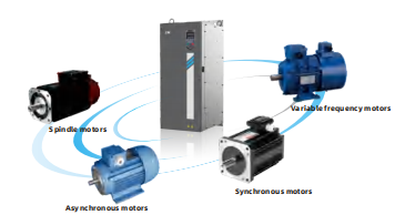
WK300 Series High Performance Vector Frequency inverter feature.
Powerful performance
High-performance vector control, high precision speed output
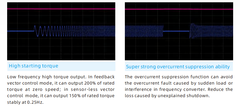
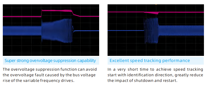
Super strong overvoltage and overcurrent suppression capability
Low-speed high-torque, improve equipment low-speed control performance
Diversified functions
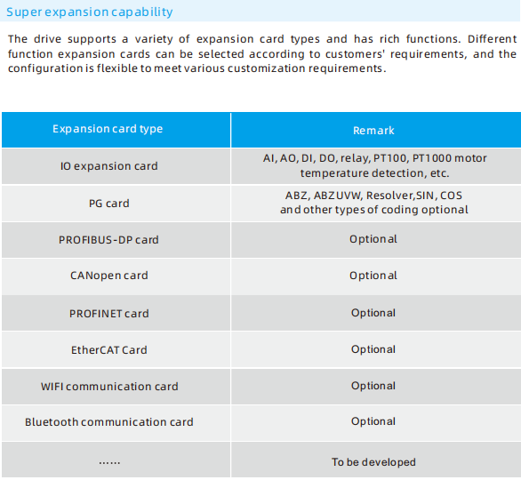
Software and hardware modular design, powerful expansion ability
High-performance, easy-to-use keyboards with a wide variety of keyboard types
Support host computer operation, reduce debugging time and difficulty
Compact structure
Full range of book-style narrow body design, high power density
Support embedded, wall-mounted, cabinet installation
Direct heat dissipation from top to bottom, multiple drives can be installed side by side device, greatly reducing the volume of the electrical cabinet
Stable and reliable
Independent air duct design, adapt to the harsh external environment
Advanced heat dissipation design to effectively ensure product thermal reliability
Strict component selection and testing procedures, and rigorous whole-machine testing to ensure product quality
Speed, torque, position control integration Torque and speed control performance
Ensure smooth operation of the machine, quick response and small torque ripple.
WK300 VFD INVERTER TECHNICAL SPECIFICATIONS
| Power input | Rated input voltage | 200V Voltage Class:single/three-phase 200V~240V | |
| 400V Voltage Class:Three-phase 380V~440V | |||
| 690V Voltage Class:Three-phase 660V~690V | |||
| Frequency | 50Hz/60Hz,tolerance ±5% | ||
| Voltage range | -15%~+15% | ||
| Voltage out-of-balance rate<3%,distortion rate as per the requirements of IEC61800-2 | |||
| Rated input current | See Section 2.3 | ||
| Power onput | Applicable motor (kW) | See Section 2.3 | |
| Rated current (A) | See Section 2.3 | ||
| Output voltage (V) | 3-phase:0%~rated input voltage,error<±3% | ||
| Output frequency (Hz) | 0.00%~600.00Hz;unit:0.01Hz | ||
| Overload capacity | G type:150%-60 seconds,P type:120%-60 seconds | ||
| Control characteristics | Control mode | V/f control Sensorless vector control (SVC) Feedback vector control(FVC) | |
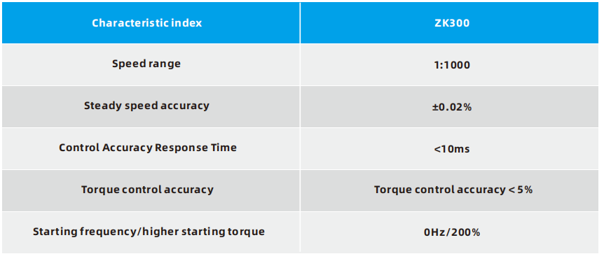
| Range of speed regulation | 1:200 (Sensor-less vector control) 1:1000(Feedback vector control) | ||
| Speed accuracy | ±0.5%(Sensor-less vector control) ±0.02%(Feedback vector control) | ||
| Torque control accuracy | 5%(SVC),3%(FVC) | ||
| Torque increase | Automatic torque lifting;Manual torque increased by 0.1-30.0% | ||
| Starting torque | 0.25Hz:150%(Sensor-less vector control) 0Hz:200%(Feedback vector control) | ||
| Basic functions | Output frequency | 0.00~599.00Hz | |
| ACC/DEC time | 0.00~30000s | ||
| Carrier frequency | 1kHz~16kHz | ||
| Frequency setting | Digital setting +control panel Communication Analog setting Terminal pulse setting | ||
| Motor start-up methods | Started from starting frequency DC brake start-up Speed tracking start | ||
| Motor stop methods | Ramp to stop Free stop | ||
| Dynamic braking capacity | Brake unit working voltage: 200V level:325-375V/400V level:650V-810V/ 690V level:1000~1200V Service time:0-100.0s;brake unit for VFD300-110kW and below can be inbuilt optionally.See table 2.3-1 | ||
| Basic functions | DC brake capacity | DC brake start frequency:0.00~600.00Hz |
| DC brake current:0.0~100.0% | ||
| DC brake time:0.0~100.00s | ||
| Input terminals | 5 digital inputs, one of which can be used for high-speed pulse input | |
| 2 analog inputs, which is voltage/current programmable | ||
| Output terminals | 1 digital output terminal, optional as high-speed pulse output terminal, can support 0.01 ~ 100kHz square wave signal output | |
| 1 analog output , voltage/current output programmable; | ||
| can output signals such as frequency setting, or output frequency, etc. | ||
| 1 Relay output terminal,drive capability:AC250V,3A;DC30V,5A. | ||
| Communication terminal | 1 channel RS485 communication , can support up to 38400bps communication rate |
| Extensions | Supports multiple I/O, relay outputs,resolver, differential and open collector photoelectric encoders, Modbus, ProfibusDP, CANopen, Profinet, EtherCAT, PT1000, PT100…. | |
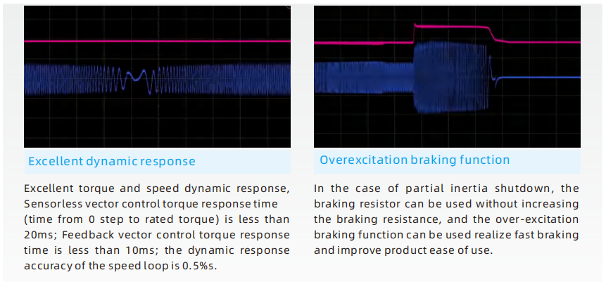
| Featured functions | Parameter copy, parameter backup, common DC bus, free switchover between two motors’ parameters, various master & auxiliary setting and switchover, flying start, a variety of Accel/Decel curves optional, brake control, 15-step speed control programmable (2-step speed supports flexible frequency command), wobble frequency control, count function, three history faults, over excitation brake, over voltage stall protection, under voltage stall protection, restart on power loss, skip frequency, frequency binding, four kinds of Accel/Decel time, motor thermal protection, flexible fan control, process PID control, simple PLC, multi-functional key programmable, droop control, autotuning,field-weakening control, high-precision torque restraint, V/f separatedcontrol | |
| Protection functions | Refer to Chapter 9-Trouble Shooting | |
| Environment | Place of operation | Indoors, no direct sunlight, free from dust, corrosive gases, flammable gases, oil mist, water vapor, water drop or salt,etc. |
| Altitude | 0~2000m. De-rate 1% for every 100m when the altitude is above 1000 meters | |
| Ambient | -10℃~50℃, The rated output current should be derated | |
| temperature | 1% for every 1℃ when the ambient is 40℃~50℃ | |
| Relative humidity | 5~95%, no condensation | |
| Vibration | Less than 5.9m/s² (0.6g) | |
| Storage | -20℃~+60℃ | |
| temperature | ||
| Others | Rated power | |
| Efficiency at rated Amps | 7.5kW and below:≥93% | |
| 11~45kW:≥ 95% | ||
| 55kW and above:≥98% | ||
| Installation | 110kW and below support wall-mounted and embedded installation (optional) | |
| 185kW and above support wall-mounted installation and cabinet installation (optional) | ||
| IP grade | IP20 | |
| Cooling method | Forced air cooling | |
Function description of the control terminals
| Category | Terminal | Terminal Name | Function Description |
| Power source | 10V-GND | +10V power supply | 1,External 10V power supply |
| 2,Generally used for external potentiometer power supply, potentiometer resistance range 1kΩ~10kΩ | |||
| 3,Maximum output current 20mA | |||
| 24V-COM | +24Vpower supply | 1,Provide +24V power supply to external unit. Generally, it provides power supply to DI/DO terminals and external sensors. | |
| 2,Maximum output current:100mA | |||
| 3,Do not use this power supply as an external power supply | |||
| Analog | AI1 | Analog input terminal | Supports 0V to 10V voltage or 0/4mA to 20mA current input, which is selected by jumper AI1(J10). The default voltage input is 0V to 10V |
| input | |||
| Digital input | DI1 | Digit input terminal 1 | 1,Multifunctional digital input, through F5-00 to F5-03 to set the function |
| DI2 | Digit input terminal 2 | 2,Supports external NPN and PNP input. You can select the input mode by using jumper DI(J1). By default, the input mode is NPN | |
| DI3 | Digit input terminal 3 | 3,DI4 can be used as a pulse input terminal. This function is optional. | |
| DI4 | Digit input terminal 4 | ||
| Analog | AO1 | Analog output terminal | Support 0V~10V voltage or 0/4mA~20mA current output, selected by jumper AO1(J4), default is 0V~10V voltage output |
| output | |||
| Digital | DO1 | Digital output | 1,DO1 open-collector output |
| output | 2,Pull-up voltage range: 5V~24V (resistance range: 1kΩ~10kΩ) | ||
| 3,Output current range:0~50mA | |||
| Relay | T1/A-T1/C | Relay T1 normally open terminal | Contact drive capacity: AC250V, 3A; DC30V, 5A |
| Output 1 | T1/B-T1/C | Relay T1 normally closed terminal | |
| Relay | T2/A-T2/C | Relay T2 normally open terminal | |
| Output 2 | |||
| 485 communication | 485+ – 485- | RS-485 | 1,Standard RS-485 communication terminals, use twisted-pair shielded cables |
| 2,Terminal resistance 120R is selected by jumper 485R. The default is no terminal resistance | |||
| communication terminal | 3,Communication filter capacitor is selected by jumper 485C. The default value is no filter capacitor |
Please kindly inform us of the required models for the WK300 Variable Frequency Inverter, and we will promptly provide you with a quotation.
| Table 2.3-1 Product model and technical data(three-phase 380V) | |||||||
| Model | Power | Output current | Input current | Matched motor | Brake | DC | |
| rating (kW) | (A) | (A) | (kW) | unit | reactor | ||
| WK300-4T-0.75B/1.5PB | 0.75GB | 0.75 | 2.5 | 3.5 | 0.75 | Inbuilt | None |
| 1.5PB | 1.5 | 3.8 | 4.6 | 1.5 | |||
| WK300-4T-1.5GB/2.2PB | 1.5GB | 1.5 | 3.8 | 4.6 | 1.5 | ||
| 2.2PB | 2.2 | 5.1 | 6.3 | 2.2 | |||
| WK300-4T-2.2GB/4.0PB | 2.2GB | 2.2 | 5.1 | 6.3 | 2.2 | ||
| 4.0PB | 4 | 9 | 11.5 | 4 | |||
| WK300-4T-4.0GB/5.5PB | 4.0GB | 4 | 9 | 11.5 | 4 | ||
| 5.5PB | 5.5 | 13 | 16.8 | 5.5 | |||
| WK300-4T-5.5GB/7.5PB | 5.5GB | 5.5 | 13 | 16.8 | 5.5 | ||
| 7.5PB | 7.5 | 17 | 22 | 7.5 | |||
| WK300-4T-7.5GB/11PB | 7.5GB | 7.5 | 17 | 22 | 7.5 | ||
| 11PB | 11 | 25 | 32.5 | 11 | |||
| WK300-4T-11GB/15PB | 11GB | 11 | 25 | 32.5 | 11 | ||
| 15PB | 15 | 32 | 41.5 | 15 | |||
| WK300-4T-15GB/18.5PB | 15GB | 15 | 32 | 41.5 | 15 | ||
| 18.5PB | 18.5 | 37 | 49.6 | 18.5 | |||
| WK300-4T-18.5GB/22PB | 18.5GB | 18.5 | 37 | 49.6 | 18.5 | ||
| 22PB | 22 | 45 | 59 | 22 | |||
| WK300-4T-22GB/30PB | 22GB | 22 | 45 | 59 | 22 | ||
| 30PB | 30 | 60 | 65 | 30 | |||
| WK300-4T-30G/37P | 30G | 30 | 60 | 65 | 30 | Inbuilt | Inbuilt |
| 37P | 37 | 75 | 80 | 37 | optional | optional | |
| WK300-4T-37G/45P | 37G | 37 | 75 | 80 | 37 | ||
| 45P | 45 | 91 | 95 | 45 | |||
| WK300-4T-45G/55P | 45G | 45 | 91 | 95 | 45 | ||
| 55P | 55 | 112 | 118 | 55 | |||
| WK300-4T-55G/75P | 55G | 55 | 112 | 118 | 55 | ||
| 75P | 75 | 150 | 157 | 75 | |||
| WK300-4T-75G/90P | 75G | 75 | 150 | 157 | 75 | ||
| 90P | 90 | 176 | 180 | 90 | |||
| WK300-4T-90G/110P | 90G | 90 | 176 | 180 | 90 | ||
| 110P | 110 | 210 | 214 | 110 | |||
| WK300-4T-110G/132P | 110G | 110 | 210 | 214 | 110 | ||
| 132P | 132 | 253 | 256 | 132 | |||
| WK300-4T-132G/160P-L | 132G | 132 | 253 | 240 | 132 | Externally mounted when needed | Inbuilt |
| 160P | 160 | 304 | 287 | 160 | |||
| Model | Power | Output current | Input current | Matched motor | Brake | DC | |
| rating (kW) | (A) | (A) | (kW) | unit | reactor | ||
| WK300-4T-160G/185P-L | 160G | 160 | 304 | 287 | 160 | Externally mounted when needed | Inbuilt |
| 185P | 185 | 326 | 306 | 185 | |||
| WK300-4T-185G/200P-L | 185G | 185 | 326 | 306 | 185 | ||
| 200P | 200 | 377 | 365 | 200 | |||
| WK300-4T-200G/220P-L | 200G | 200 | 377 | 365 | 200 | ||
| 220P | 220 | 426 | 410 | 220 | |||
| WK300-4T-220G/250P-L | 220G | 220 | 426 | 410 | 220 | ||
| 250P | 250 | 465 | 441 | 250 | |||
| WK300-4T-250G/280P-L | 250G | 250 | 465 | 441 | 250 | ||
| 280P | 280 | 520 | 495 | 280 | |||
| WK300-4T-280G/315P-L | 280G | 280 | 520 | 495 | 280 | ||
| 315P | 315 | 585 | 565 | 315 | |||
| WK300-4T-315G/355P-L | 315G | 315 | 585 | 565 | 315 | ||
| 355P | 355 | 650 | 617 | 355 | |||
| WK300-4T-355G/400P-L | 355G | 355 | 650 | 617 | 355 | ||
| 400P | 400 | 725 | 687 | 400 | |||
| WK300-4T-400G/450P-L | 400G | 400 | 725 | 687 | 400 | ||
| 450P | 450 | 820 | 782 | 450 | |||
| WK300-4T-450G/500P-L | 450G | 450 | 820 | 790 | 450 | ||
| 500P | 500 | 860 | 835 | 500 | |||
| WK300-4T-500G/560P-L | 500G | 500 | 860 | 835 | 500 | ||
| 560P | 560 | 950 | 920 | 560 | |||
| WK300-4T-560G/630P-L | 560G | 560 | 950 | 920 | 560 | ||
| 630P | 630 | 1100 | 1050 | 630 | |||
| WK300-4T-630G/710P-I | 630G | 630 | 1100 | 1050 | 630 | / | Standard input reactor |
| 710P | 710 | 1260 | 1198 | 710 | |||
| WK300-4T-710G/800P-I | 710G | 710 | 1260 | 1198 | 710 | ||
| 800P | 800 | 1500 | 1426 | 800 | |||
| Table 2.3-2 Product model and technical data(three-phase 220V) | |||||||
| Model | Power | Output current | Input current | Matched motor | Brake | DC | |
| rating | (A) | (A) | (kW) | unit | reactor | ||
| (kW) | |||||||
| WK300-2T-0.75GB | 0.75 | 4 | 4.8 | 0.75 | Inbuilt | None | |
| WK300-2T-1.5GB | 1.5 | 7 | 8.8 | 1.5 | |||
| WK300-2T-2.2GB | 2.2 | 9.6 | 12 | 2.2 | |||
| WK300-2T-4.0GB | 4 | 16 | 21 | 4 | |||
| WK300-2T-5.5GB | 5.5 | 20 | 26 | 5.5 | |||
| WK300-2T-7.5GB | 7.5 | 30 | 39 | 7.5 | |||
| WK300-2T-11GB | 11 | 42 | 55 | 11 | |||
| WK300-2T-15G | 15 | 55 | 60 | 15 | Inbuilt | Inbuilt | |
| WK300-2T-18.5G | 18.5 | 70 | 75 | 18.5 | optional | optional | |
| Table 2.3-3 Product model and technical data( single-phase 220V) | |||||||
| Model | Power | Output current | Input | Matched motor | Brake | DC | |
| rating | (A) | current | (kW) | unit | reactor | ||
| (kW) | (A) | ||||||
| WK300-2S-0.75GB | 0.75 | 4 | 8.2 | 0.75 | Inbuilt | None | |
| WK300-2S-1.5GB | 1.5 | 7 | 14 | 1.5 | |||
| WK300-2S-2.2GB | 2.2 | 9.6 | 23 | 2.2 | |||
| WK300-2S-4.0GB | 4 | 16 | 33 | 4 | |||
| WK300-2S-5.5GB | 5.5 | 20 | 40 | 5.5 | |||
| WK300-2S-7.5GB | 7.5 | 30 | 58 | 7.5 | |||
| WK300-2S-11GB | 11 | 42 | 84 | 11 | |||
| WK300-2S-15G | 15 | 55 | 110 | 15 | Inbuilt | Inbuilt | |
| WK300-2S-18.5G | 18.5 | 70 | 140 | 18.5 | optional | optional | |


Reviews
There are no reviews yet.